
SIMPLE TO BUILD KEYER FOR MOBILE OR STATION USE
By Robert Parker VE3RPF
Today we discard virtually everything once we’ve determined it no longer serves any practical use. Take the computer for instance. Think back to how many generations of computers you’ve probably gone through before you ended up with the one you’re using now! What happened to the other ones? If they were not given to family members or sold at a great loss, they probably ended up in some landfill in some third world country were someone right now is melting the boards to get the gold from the gold plated connectors.
It certainly would be nice if you could take that antiquated computer and do something useful with it again. A nice thought but unfortunately not too many useful compatible parts can be reused. This is called planned obsolescence in industry and is designed to make sure you buy a newer machine if you wish to keep up. Now what if you could reuse a component from your old system and use it in a way that is totally unrelated to its intended function, yet augment your radio hobby for practically nothing? I think I’ve got you’re attention because like me, all Hams like a great deal or better yet, free stuff. In fact I’ll bet most of you who are reading this right now have at least one of these in your junk-box right now! What I’m talking about is an old ball mouse that you’ve used for years and threw it in the junk-box because either the mouse worn out or you replaced it with the latest digital light mouse. For only a small investment of your time, you can convert a ball mouse for use as a keyer or key for mobile/portable or station use.
It’s simple and works great!
Getting Started
To begin, you’re going to need to locate that old ball mouse. For those who, on the slight chance, do not have one, ask a friend, get one at a swap-meet or computer store that deals in used relics etc.
Once you’ve located a ball mouse, you’re going to need to disassemble it. Usually there are at least two screws on the underside (some may have four). Remove the screws and separate the top and bottom halves. Inside, you’ll see a circuit board, the ball and two disk like things call the encoders.
Remove the ball and since you won’t need it, do whatever you like with it. Next remove the circuit board by lifting it out of the lower half of the mouse. This should come out easily. If not, look for any securing screws or plastic hangars preventing its release and compromise them. You’ll notice that there is a plug on the board where the mouse cable attaches. This will be referred to as the mouse cable plug and the connections underneath, the mouse cable socket. See Fig1 For now, separate these by unplugging the cable. This will make it easier to flip the board around when soldering the switch wires.
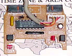
Fig 1
Notice on this particular mouse there are two micro switches (top of board). These are the keying elements. Some mice come with three switches. Only concern yourself with the two outer switches.
The underside of the board has all the solder connections and is where wires will be placed to activate the switches for the keyer. Usually mice switches require power to operate since they have special de-bounce circuitry that prevents false switching. In this application, de-bouncing is not a concern.
Flip the board upside-down to reveal the solder connections. See Fig 2 Note at each switch, two connections are soldered to the same trace while the third is not. The two that are soldered together will be used as the common for the keyer. The other connections will represent either dit or dah. Make note where the common trace connects to the mouse cable socket. You will have to turn the board right side up to zero in on its position. Write it down on a piece of paper for later on.

Fig 2
It will be necessary to solder a wire from the non-common pin on each switch to the mouse cable socket. Before doing this, get a sharp Xacto knife and open the trace of each center pin of the two switches. This must be done to ensure an open circuit condition exists when the switches are not depressed otherwise the onboard circuitry could represent a low enough resistance to trigger the keying circuitry inside the transceiver.
Heat up a soldering iron and get a small piece of wire for each center pin on the switch, solder an end of each wire to the pin. Solder the other end of these wires to the extreme ends of the mouse cable socket. The left switch is soldered to the extreme left of the mouse cable socket and the right switch is soldered to the extreme right mouse cable socket. You should end up with something that looks like Fig 3.
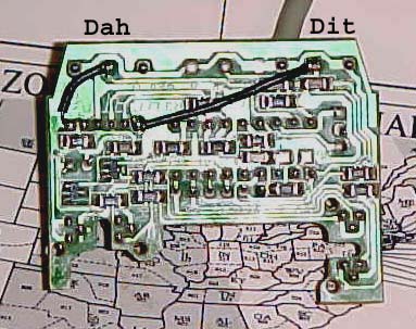
Fig 3
Turn over the board and install the mouse cable into the mouse cable socket. Make note on a piece of paper the colors of the wires that were soldered as well as the common switch trace. Install the board back into the bottom shell of the mouse and then the top half of the mouse. Do not put in the screws yet.
Cut the end of the mouse cable and expose the multi colored wires. Bend back the wires that are not used. You should be left with three wires (common, left mouse button for dit and right mouse button for dah). Slide the sleeve of the mini stereo plug over the wires and out of the way. Strip about 1/8” insulation form each of the three wires. Solder these wires onto the mini stereo plug so the result matches Fig4. Of course if you prefer reverse connections of dit and dah solder accordingly.
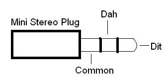
Fig 4
Using an ohm meter, set it for beep so a tone is heard if there is continuity. If the meter you’re using does not have a beep function, make sure you can read the meter for lowest resistance. First check all rings on the plug to ensure there are no shorts. If there are, you’ll have to check the board for solder bridges and fix them. If everything is ok, connect one lead from your ohmmeter to the common or inner most ring of the mini stereo plug. Connect the other to the dit or tip of the mini stereo plug. Depress the left mouse button and verify there is continuity. Do the same for the dah center ring of the mini stereo plug and depress the right mouse switch to verify continuity. If all these checks pass, take your ohm meter off beep and do a reading of all stereo plug combinations to ensure a resistance reading of at least several Meg ohms or more. If the reading is much less, the trace cut needs to be done again and rechecked. Once you’re satisfied, put back the screws into the mouse case and that’s it.
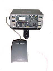
Elecraft K1 with MoooseKeyer
For mobile operations, you can connect a Velcro strap to the MoooseKeyer and attach it to your thigh for effortless keying. It takes a little practice to get use to but in no time you’ll be sending beautiful code.
No one will believe what you’re using however.
Have fun 73’s